Categories
Networking

SSH Tunneling Made Easy!

I think I have understood the concept of SSH tunneling.  Tunneling is encapsulating one network protocol inside another. Consider the following scenario to understand. Lets say three computers A,B and C are connected in a network. B is allowed to connect to C but not A. How would A connect to C ? It can disguise as B and connect to C, right ? The disusing is called Tunneling, hiding or encapsulating.

A -> B -> C

Tunneling tools are available in market, the most readily available tool is ssh client. SSH client in the UNIX/Linux machines have capability to to do SSH tunneling, i.e, it provides feature to hide network traffic in SSH connections (tunnel). This is called SSH tunneling. SSH is secured connection, so the connection tunneled through it, is also secure.

SSH Tunneling is the most exploited method to hack  networks.  It is also used to by pass corporate firewalls. We can understand this in detail using below network diagram.

SS_Tunnel

This is a typical network diagram, Corporate network is hidden behind the firewall. The firewall has rules – which allows/deny incoming and outgoing connection. Client, SSHHost, WebHost, DBHost are nodes which are running SSH Server, Web server and Database server respectively. All the nodes are connected with each other and accessible over the network ( or internet ).

Most corporate firewall allows outgoing connections at port:80, 443. These are port for web server and secured web (https). If some corporate user wants to connect to web server, it can connect, the firewall would allow http connection at port 80. But, if the user wants to connect to a database server (at port 1521) outside firewall, the firewall would deny the connection.

SSH (local) Tunneling  can allow the corporate user to connect the Database server.  All we have to do is to create a connection from a client (here Webshot) to SSHHost server.

Webhost $ ssh -L 443:DBHost:1521 sshuser@SSHhost.

This will create a connection from Webhost to SSHhost and it will create a tunnel from Webhost to DBhost as well. The tunnel is actually a server process on Webshost listening for incoming connection on port 443 and redirecting to DBhost. The firewall would think that the request is made on the port 443, but eventually it will be redirected to database server on port 1521. In this case the Webhost is called jump server.

SSH local tunneling can give access to servers behind the firewall. But, how can we access servers inside the corporate firewall. Lets assume we want to show a website available in corporate intranet to outside world. This can be achieved using SSH reverse tunneling.  For SSH reverse tunneling to work, the the firewall should allow to connect to a ssh server outside firewall (port 22 should be allowed on the Firewall). Create a ssh connection from a computer (localhost) inside the firewall.

corporate computer # ssh -R 9999:localhost:80 sshuser@SSHHost

This would create a ssh connection from the machine inside, corporate to the SSHHost server. Additionally it would create a server on SSHHost at the port 9999. Incoming connection to SSHHost on port 9999 would be redirected to corporate computer port 80. We can access the website hosted on corporate computer (localhost) from outside. Hit http://SSHhost:9999 in the web browser on the client. it will open website hosted within intranet.

The SSH Server on SSHHost should have “GatewayPorts yes” in the file /etc/ssh/sshd_config. The computer we are targeting with in the firewall should also have “GatewayPorts yes”.

The concept of tunneling is old and not well documented.  It took me some time to understand it. Feel free to ask questions and share your comments.


Categories
ESP8266

Introducing ESP-01 Module.

There are literally hundreds of posts and forums on introducing and connecting ESP-01 module to computers and program them. I am writing my own version, just to keep note of my own work. I would be glad If it helps somebody to learn and understand this tiny module.

You can refer to post to understand about ESP modules in general. ESP-01 is the first version of module, and I guess this is the most popular of all the versions. The obvious reasons are cost and ease of operation. The module is available in less then 325₹ (~5$) and it can be made operational with some accessories in less then 650₹ (~10$).

The outline of the module is given below. It has 8 pins.

  1. 2 power supply pin (VCC & GND).
  2. 2 pins for serial transmission (TX & RX).
  3. 2 pins for GPIOs ( GPIO0 & GPIO2).
  4. 2 Enable and Reset pin (CH_PD & RST).

esp01_outline ESP-01

At this point, Many folks would be wondering what is GPIOs, Serial transmission, Enable and Reset pins.

In short, GPIOs are General Purpose Input Output – These are standard pins found in almost all micro-controllers. This module has 2 GPIOs, other have many of them. These pins can be made to read input or write (send) output. Same pin can act as both input or output.

Serial transmission is another standard device to device communication protocol, pin TX used for transmission and RX for receiving data. Use wiki to learn more about them.

The Enable and Reset pins are used to make the device operational. CH_PD is kept high for normal operation, this is connected to CHIP_EN of internal chip, it must be kept high to make the chip operational. RST is reset pin, keep it high for normal operation and toggle it high to low to high for hard resetting the module.

GPIO0 decides the mode of operation of the device, at time of reboot (resetting) if the GPIO0 is low, the device enters flashing mode, i.e. new firmware ( code or binary ) can be loaded into the micro controller. when it is high, the device executes existing code. Leave GPIO2 unconnected if you are not using it for I/O.

I can keep on writing how to connect these devices  to computer and program, but it would be too much for one single post. So, I am keeping the connection for the next post.

Categories
Networking Uncategorized

Route – How the IP packets are sent?

A computer system or any SOC (System on chip) device with network interfaces uses routing tables to connect to other networks.  A routing table is system wide (tabular) configuration which take cares how the IP packets would be send to another system.

Usually, every network device (laptops, routers, switches) has routing table configured manually or automatically.

At a ubuntu machine, routing table looks something like below. Every entry says which Interface (Iface) would be used to send an network packet with certain IP. The machine in the snapshot has two network interface (eth0 & tun0).

ubuntu_route

The default route (0.0.0.0 in windows) is used for all the non-matching IP , i.e, All the internet traffic goes via default interface. A windows routing table looks like below.

windows_route.jpg

You can add a new route (static routing) to windows machine using route ADD command. (You need admin privilege ).

route ADD 192.167.173.0 MASK 255.255.255.0 192.168.0.191

Now, if you ping 192.168.173.1, it would be routed to interface having IP address 192.168.0.191).  The interface would further transfer the packet to its default gateway.

You reach internet server via multiple gateways, switches and routers. All of them have a routing table configured. Windows trace route command can tell which systems have been used to reach the internet server.


Categories
ESP8266

ESP8266 – Wonder Tool for IOT

Internet of Things (IOT) has been in the market for some time now. It is no more a buzz word and we are surrounded by it without realizing it. I am interested in connecting things using wire/wireless and making communication happen between them. This is what IOT is doing, connecting objects with each other. Internet is just working as another wire/wireless tool to connect these objects. Once objects are connected they can communicate, controlled by human or machine.

ESP8266 module is one tool which acts as a bridge between connecting objects. It is a low cost WiFi chip with fully functional tcp/ip stack and a micro controller on it. Connect this device to any WiFi, add some code on micro controller and control things – This is what IOT is connecting and controlling anything from anywhere.

This device comes in 13 version (ESP-01 to ESP-13). All the devices have multiple i/o pins. The simplest is ESP-01 with 8 Pin.

ESP-01 and Pin diagram

Esp01

Programming and connecting this device is very easy. It needs 3.3 v dc power supply, which can be generated using two 1.5 v AA dry cell or can be drawn from a supply unit. The power consumption is something which needs to be thought based on the time duration for which the device needs to be operational. It can be reduced putting the device in sleep mode. Another important aspect of power consumption  is the connection to the WiFi. It becomes power hungry when connecting to the WiFi.

The details of connecting ESP modules will be discussed in another post. It can be connected to relays, sensors, arduino/raspberry-pi boards to perform various IOT operations. The next post in this series is “Introducing ESP-01 Module”, which explains the details of first version of the module.

Categories
Linux Ubuntu

CMUS – A command line music player.

cmus is command line based music player for linux based operation system. It supports various output methods by output-plugins. It can be controlled from outside using cmus-remote.

We can use cmus for playing audio on local drive, audio hosted on network or any live stream. I have used cmus to play online radio stations.

There are 7 views in cmus. Press keys 1-7 to change active view.

Library view (1) , Sorted library view (2) , Playlist view (3) , Play Queue view (4) , Browser (5) ,Filters view (6) , Settinsgs view (7)                                                                                                                               Multiple Views of cmus

cmus_all_views

Cmus Control                                                                                                                                       cmus is conrolled using commands and key presses. Press “:” to enter comand line and “Esc” to come out of command mode. Commands can be auto completed by pressing “tab”.

Press “a” in command mode to add any music to library. Use following key presses to copy marked or selected tracks from views 1-5

a copy tracks to the library in view (1-2)                                                                                          y copy tracks to the playlist in view(3)                                                                                                e append tracks to the play queue in view (4)                                                                                  E prepend tracks to the play queue in view (4)

Common cmus commands

q quit -i
:q exit cmus.
b player-next
c player-pause
x player-play
z player-prev
v player-stop
+ volume +10%
– volume -10%

cmus-remote

This is a utility to control running cmus from outside cmus process.  If no argument is given it connect to local cmus socket (~/.cmus/socket). It can also connect o external cmus using  “–server SOCKET”  argument.

Some common commands to control are

-p Start playing.
-u Toggle pause.
-s Stop playing.
-n Skip forward in playlist.
-r Skip backward in playlist.
-R Toggle repeat.
-S Toggle shuffle.
-v VOL Change volume.
-k SEEK Seek.
-Q, Get player status information
-l Modify library instead of playlist.
-P Modify playlist (default).


cmus playlist

You can create a playlist and put in cmus home. It will be visible in playlist view(3). Some of the bollywood channels are listed below.

pi@raspberrypi:~/.cmus $ cat > playlist.pl

http://50.7.77.114:8296/

http://174.36.206.197:8198/

http://198.100.149.27:8012/

http://uk2.internet-radio.com:8043/live

http://69.64.61.173:8057/stream

http://50.7.77.114:8296

http://5.9.66.201:8896

http://185.66.249.48:9600/stream

http://69.162.111.146:9960

http://192.240.102.133:8512/stream


Categories
Linux Networking Python Ubuntu

MQTT Python Client

In this article, I want to create a python module which would connect to mosquitto server. We can connect a MQTT client as subscriber or publisher of message.

Mosquitto python module has been donated to Eclipse Paho project, which is open-source client implementations of MQTT.  This module can be installed using pip command.

$ sudo pip install paho-mqtt

Subs.py – The code given below is subscribe module. You can look at comment to understand in detail.


#The line imports python mqtt module.
import paho.mqtt.client as mqtt

#Here we initilize variables used in the code.
server = "192.168.0.XXX"
port = 8883
keep_live = 45
topic = "msgTopic"

# Define routines to register.
# Client - The instance at the client side.
# userdata - Data to be passed by the user.
# flags - response flag sent by the server.
# rc - Return code, 0 is successful connection.
# mid - message id
# granted_qos - Quality of service granted by the server, default 0.
# payload - the message received on the topic.
def on_connect(client, userdata, flags, rc):
 mqttc.subscribe(topic, 0)
def on_subscribe(client, userdata, mid, granted_qos):
 print("Subscribed to: "+str(mid)+" "+str(granted_qos))
def on_message(client, userdata, msg):
 print(msg.topic+" "+str(msg.qos)+" "+str(msg.payload))

# Initilize a client instance and ser password for the connection.
mqttc = mqtt.Client()
mqttc.username_pw_set(username="username",password="password")

# register the routines.
mqttc.on_message = on_message
mqttc.on_connect = on_connect
mqttc.on_subscribe = on_subscribe

# connect to the server and wait for message.
mqttc.connect(server, port, keep_live)
mqttc.loop_forever()

Pubs.py – The code given below is publisher module. You can look at comment to understand in detail.

#The line imports python mqtt module.
import paho.mqtt.client as mqtt

#Here we initilize variables used in the code.
server = "192.168.0.191"
port = 8883
keep_live = 45
topic = "msgTopic"

# Connect and publish modules
def on_connect(client, userdata, flags, rc):
 mqttc.subscribe(topic, 0)
def on_publish(client, userdata, mid):
 print "Message Published..."

# Initilize a client instance and ser password for the connection.
mqttc = mqtt.Client()
mqttc.username_pw_set(username="mqtt",password="mqtt")

# register the routines.
mqttc.on_publish = on_publish
mqttc.on_connect = on_connect

# Connect and publish the message on a topic.
mqttc.connect(server, port, keep_live)
mqttc.publish(topic,"Hello! How are you?")
mqttc.disconnect()
 Output – Below is the Publish and Subscribe module in action on raspberry pi.
subs_pub
Categories
Linux Ubuntu

MQTT

MQTT is simple publish subscribe message broker, which is used for IOT based machine to machine (M2M) communication. It is simple to use. It needs a MQTT server, which can be hosted on any linux or windows machine.

Execute The following line with root privilege, it would import security code and add to local key repository and install mosqitto service.

$wget http://repo.mosquitto.org/debian/mosquitto-repo.gpg.key
$sudo apt-key add mosquitto-repo.gpg.key
$cd /etc/apt/sources.list.d/
$sudo wget http://repo.mosquitto.org/debian/mosquitto-wheezy.list
$sudo apt-get install mosquitto

Making mosquitto secure – Add below lines to the file /etc/mosquitto/mosquitto.conf. This would make the mosquitto listen on port(8883) at all the interfaces connected to Raspberry pi.

listener 8883 0.0.0.0
password_file /etc/mosquitto/pwfile

Update the password file with the username you want to connect to the mosquitto service and restart the mosquitto service.

$ sudo mosquitto_passwd -c /etc/mosquitto/pwfile mqtt
Password:
Reenter password:
$ sudo service mosquitto restart
$ ps -aef | grep mosq
mosquit+ 2150 1 0 09:55 ? 00:00:00 /usr/sbin/mosquitto -c /etc/mosquitto/mosquitto.conf


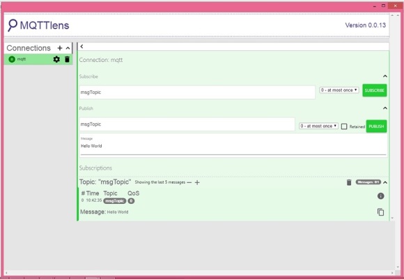
Testing the service – You can use many clients, e.g. python paho-mqtt, android based client, online client. I have used chrome based app called MQTTLens. It can be found on chrome app store.

Add a New connection

connection

Subscribe & Publish

publish_subscribe

To remove mosquitto run apt-get purge.

$sudo apt-get purge mosquitto

There can be multiple use of MQTT, I will use this to communicate with raspberry-pi, ESP8266 and Arduino modules in coming posts.


Categories
Linux Raspberry Pi

Raspberry Pi

This little credit card size ARM based computer has intrigued me since the time I held it first time in my hand. It just happened by chance, once while browsing through Amazon I ordered it and since then it has become my favorite.

This little piece of hardware gives wings to your imagination, you can do everything you wished right from OS level software experiments to hardware level things.

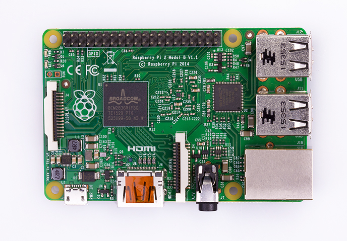
Raspberry Pi – 2 Model B

It has got 4 USB ports with RJ45 (LAN interface), HDMI and audio visual port. It needs a micro-sd card and external 5v supply. You can use any 5v, 1 AMP or above power supply. Any mobile charger with micro usb port would work fine. There are choice of OS available on here. However, I have used raspbian since beginning, because of support and help available online. Raspbian is debian based Linux distribution for raspberry pi.

Categories
Uncategorized

First blog post

This is your very first post. Click the Edit link to modify or delete it, or start a new post. If you like, use this post to tell readers why you started this blog and what you plan to do with it.